- Title
-
reg6 is required for branching morphogenesis during blood vessel regeneration in zebrafish caudal fins
- Authors
- Huang, C., Lawson, N.D., Weinstein, B.M., and Johnson, S.L.
- Source
- Full text @ Dev. Biol.
|
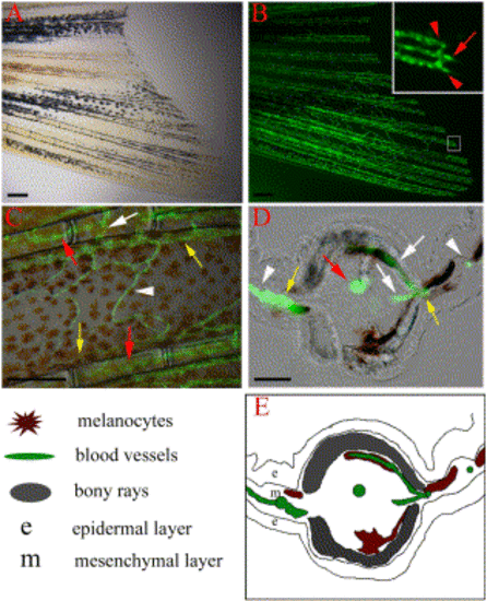
Vasculature of the zebrafish caudal fin. TG(fli1:EGFP)y1 fish express EGFP in blood vessel endothelial cells. (A) Bright field image of the ventral half of the caudal fin of an adult TG(fli1:EGFP)y1 fish and (B) epiflourescence image of the same fin, revealing the vasculature. (Inset) Higher magnification of the distal end of a fin ray (boxed region) shows that each fin ray is associated with one artery (red arrow) in the center of the ray and two veins (red arrows) adjacent to the bony ray. (C) High magnification image shows the intervessel commissures within the same ray (white arrow), which connect artery to vein as well as vein to vein. The interray vessels (white arrowhead) connect vein to vein of adjacent rays. (D, E) Cross-section through a fin ray shows the artery in the center of intraray mesenchyme (red arrow), while the veins are in interray mesenchyme adjacent to the bony rays (yellow arrows). Intervessel commissures (white arrows) and interray vessels (white arrowheads) are also visible in this section. Explanatory diagram is shown in (E). Scale bars, 200 μm in (A, B, C), 20 μm in (D). |
|
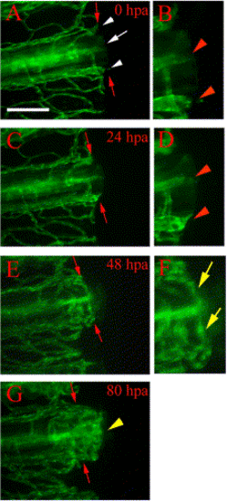
Vessel healing and anastomosis. Time-lapse images from a representative regenerating fin ray of TG(fli1:EGFP)y1 show healing and anastomosis of amputated blood vessels during early regeneration. (A) After amputation (0 hpa), severed vessels exhibit openings at the amputation plane (white arrow, artery; white arrowheads, veins). (B) Higher magnification of the distal ends of the severed vessels in (A) show the openings (red arrowheads). (C) These vessels are sealed by 24 hpa (note rounded ends) and sprouts (arrowheads) are frequently observed in (D) enlarged image of the amputation plane. (E) By 48 hpa, cut ends of blood vessels have formed anastomotic bridges between the artery and veins within the same fin ray. Blood flow has resumed through these bridges by this stage (not shown). (F) Higher magnification of the reconnected vessels of (E) shows anastomotic bridges connecting the artery and the two veins (yellow arrows). (G) By 80 hpa, we observe new blood vessels sprout from the distal face of anastomotic bridges (yellow arrowhead). Red arrows point to amputation plane. Diffuse green is autofluorescence from fin ray (possibly bone matrix). Scale bar, 100 μm. |
|
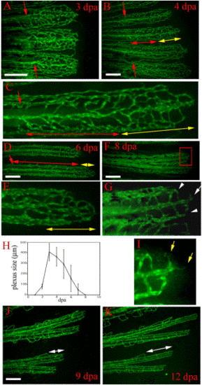
Vasculature plexus formation, plexus remodeling, and late regenerative angiogenesis. Regenerating blood vessels in wild-type TG(fli1:EGFP)y1 form plexuses. (A) In 3-dpa regenerates, the regenerating vasculature of each fin ray (three fin rays are shown) consists of a plexus with dense unstructured vessels extending distally from the amputation plane (red arrows). (B) By 4 dpa, the plexus is remodeled into distinguishable arteries and veins in the proximal regenerate (region delineated by red double-headed arrow). A vasculature plexus is still present at the distal end (region delineated by yellow double-headed arrow). Higher magnification of one fin ray of this regenerate is shown in (C). (D) Coincident with plexus remodeling, the plexus becomes smaller (region delineated by yellow double-headed arrow in D and E) in later regenerates as shown in a 6-dpa regenerate. Higher magnification of the delineated plexus in (D) is shown in (E). (F) Low magnification and (G) high magnification of the distal end of an 8-dpa regenerate show that the plexus has been entirely remodeled into arteries (white arrow in G) and veins (white arrowheads in G). (H) The plexus length (as denoted by yellow double-headed arrows in B–E) reaches a maximum of 400-500 µm at 3 dpa and disappears by 8 dpa. After 8 dpa, vessel growth proceeds by sprouting angiogenesis without a plexus intermediate, which we refer to as late regenerative angiogenesis. (I) Enlarged boxed region of the 8 dpa regenerate in (F) shows sprouts (yellow arrows) formed at the distal end of the growing vessel. (J and K) The same regenerating fin rays imaged at 9 dpa and then again at 12 dpa show that regenerating vessels grow without a plexus intermediate. Amputation plane outside field of view. White double-headed arrows denote the distal growing fin ray. Scale bar, 200 μm. |
|
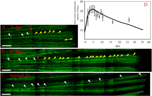
Intervessel pruning. Following plexus remodeling, the proximal regenerate undergoes intervessel pruning. In 5-dpa (A) and 11-dpa (B) TG(fli1:EGFP)y1 regenerates, the number of intervessel commissures in the regenerate (yellow arrowheads) is significantly higher than in the stump (white arrowheads) or in the normal fin (C). The yellow double-headed arrow delineates the plexus. (D) Intervessel commissure density in a regenerating fin. Intervessel commissures reach a maximal density at 5 dpa (30 commissures/mm) and are gradually pruned back to the density of a normal fin (∼10 commissures/mm, 0 dpa). Scale bar, 200 μm. |
|
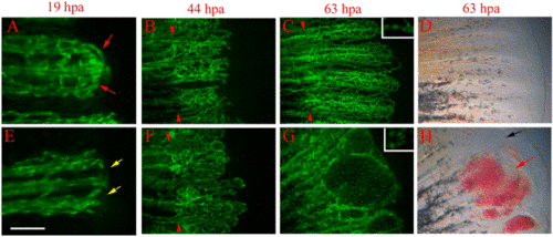
reg6 mutants have defects during anastomosis and plexus formation. Time-lapse images of wild-type TG(fli1:EGFP)y1 (A–D) and reg6;TG(fli1:EGFP)y1 (E–H) regenerates show that reg6 regenerates fail to complete anastomosis before outgrowth and later fail to form plexuses during blood vessel regeneration. (A) and (E) show 19-hpa regenerates (33°C) at which stage the wild-type regenerates (A) have finished anastomosis (red arrows), while reg6 regenerates failed to do so (E, yellow arrows). By 44 hpa (33°C), the regenerating vessels form plexuses in wild-type regenerates (B), but those in reg6 mutants grow out without forming plexuses. Instead, they form blisters with few branches (F). In 63-hpa reg6 regenerates (33°C), some blisters that developed at the distal ends of regenerating vessels (G) are filled with blood cells (red arrow in H) and some remain clear (black arrow in H), which can easily be perceived in bright field. Similar blisters are typically never seen in wild-type regenerates at the same stages (C, D). Insets in (C) and (G) are higher magnification images to show distance between nuclei (green foci) of endothelial cells in wild-type and reg6 regenerates, respectively. Red arrowheads point to amputation planes. Scale bar, 100 μm for (A, E); 200 μm for (B, F); 300 μm for (C, D, G, H). |
|
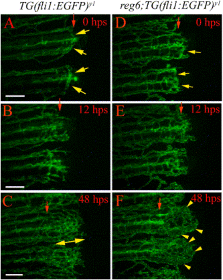
reg6 function is required for plexus formation. In the temperature up-shift experiment, wild-type TG(fli1:EGFP)y1 (A–C) and reg6;TG(fli1:EGFP)y1 (D–F) fish were allowed to complete anastomosis at the permissive temperature (20°C) and were then shifted to the restrictive temperature (33°C). In wild-type animals, the regenerating vessels form anastomotic bridges at the time of shift (A). By 12 h postshift (hps), multiple distally extending sprouts grow out from the distal face of the anastomotic bridges (B). The regenerating vessels in wild-type animals develop normal plexuses 48 h after shift to the restrictive temperature (C). In contrast, although the regenerating vessels in reg6 mutants had successfully completed anastomosis at the time of shift (D, regenerates shifted at 77 hpa are shown), they developed swollen vessels within 2 days at the restrictive temperature (F). hps, hour post shift. Red arrows, amputation plane; yellow arrows, anastomotic bridges; yellow arrowheads, swollen vessels; double-headed arrow, plexus. Scale bar, 100 μm. |
|
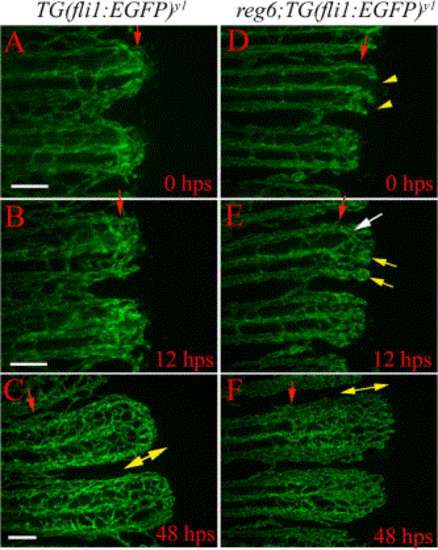
Temperature down-shift experiments show that anastomosis can be delayed with no apparent consequence to the plexus formation. While wild-type fish (A–C) always complete anastomosis successfully and develop normal plexuses in these experiments, most regenerating vessels in reg6 mutants (D–F) had failed to complete formation of anastomotic bridges (D) at the time of shift (26 hpa) (yellow arrowheads point out the absence of anastomotic bridge at amputation plane; also see Table 1). (E) Although the vessels developed small bulbs at the distal ends (yellow arrows), they were able to form anastomotic bridges at a more distal position (white arrow) 12 hps. (F) These vessels developed normal plexuses within 2 days after shift to the permissive temperature. hps, h postshift. Red arrow, amputation plane; yellow arrow, swollen vessels; double-headed arrow, plexus. Scale bar, 100 μm. |
|
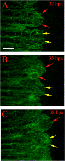
Regenerating vessels in reg6 mutants show defects in branching. Time-lapse images from regenerating vessels of reg6;TG(fli1:EGFP)y1 show defects in branching. (A) At 32 hpa (33°C), the regenerating vessels in reg6 mutants grow out with few branches and develop small bulbs at distal ends of individual arteries and veins (red and yellow arrows). These bulbs continue to grow through 35 hpa (B) and then form enlarged blisters a few hours later (C, red and yellow arrows) with fewer branches than wild type (also see Table 1). Note vessels denoted by red arrows fuse, while vessels denoted by yellow arrows remain distinct. Scale bar, 100 μm. |
|
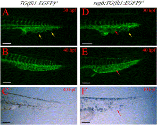
Branching defects in developing caudal veins in reg6 embryos. (A) A wild-type TG(fli1:EGFP)y1 embryo at 30 h postfertilization (hpf) (33°C) shows numerous branches (yellow arrows) in the developing caudal vein. (B) These branches develop into a plexus within a few hours and the plexus persists for several days during embryogenesis (a 40-hpf embryo is shown). (C) Bright field image of (B). (D) The developing caudal vein in reg6;TG(fli1:EGFP)y1 embryo at 30 hpf (33°C) shows fewer branches (yellow arrow) and a developing sinus (red arrow). (E) By 40 hpf, the developing caudal veins in reg6;TG(fli1:EGFP)y1 embryos become swollen and form a sinus (red arrow). (F) Bright field image of (E); red arrow, developing sinus. Anterior to the left and dorsal up. hpf, hour post fertilization. Scale bars, 100 μm. |
Reprinted from Developmental Biology, 264(1), Huang, C., Lawson, N.D., Weinstein, B.M., and Johnson, S.L., reg6 is required for branching morphogenesis during blood vessel regeneration in zebrafish caudal fins, 263-274, Copyright (2003) with permission from Elsevier. Full text @ Dev. Biol.

