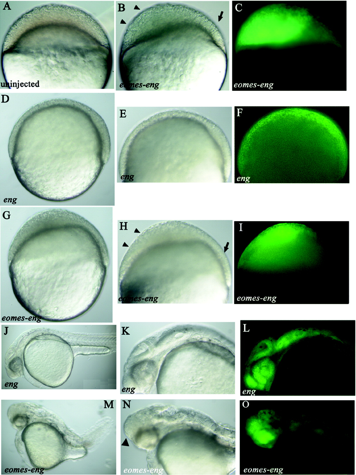
Fig. 1
eomes-eng inhibits epiboly. A-O: All views lateral. J-O: anterior toward the left. Construct injected, if any, is indicated in the bottom left corner. A-C: Embryos at 30% epiboly (4.7 hours postfertilization [hpf]), (D-I) embryos at 60% epiboly (6.5 hpf). A: Uninjected control. B: Embryo injected with gfp and eomes-eng RNA. Arrowheads indicate the region of the blastoderm that has failed to thin, and the arrow indicates the normal region of the blastoderm. C: Same embryo as in B showing green fluorescent protein (GFP) fluorescence. The region indicated by the arrowheads in B is where most of the GFP expression is located. D: Control embryo injected with gfp and eng RNA. E: Higher power view of embryo in D. F: Same embryo as in E, showing that GFP fluorescence is distributed throughout the blastoderm. GFP-positive cells are intermingled with unlabeled cells. G: Embryo injected with gfp and eomes-eng RNA. H: Higher power view of embryo in G. Arrowheads indicate region of the blastoderm that has failed to thin, and the arrow indicates the normal region of the blastoderm. I: Same embryo as in H, showing GFP fluorescence. The region indicated by the arrowheads in H is where most of the GFP expression is located. J-O: Embryos at 1 day postfertilization. J: Control embryo injected with gfp and eng RNA. K: Higher magnification of J, showing the head region. L: Same embryo as in K, showing evenly distributed GFP fluorescence. M: Embryo injected with gfp and eomes-eng RNA. N: Higher magnification of M, showing abnormal head region. O: Same embryo as in N showing GFP fluorescence concentrated in the anterior portion of the head.
Image
Figure Caption
Acknowledgments
This image is the copyrighted work of the attributed author or publisher, and
ZFIN has permission only to display this image to its users.
Additional permissions should be obtained from the applicable author or publisher of the image.
Full text @ Dev. Dyn.

